PEDDLE-POWERED KORT-NOZZLED WATERCRAFT
BACKGROUND—DESCRIPTION OF RELATED ART
Kayaks are traditionally powered by the use of a paddle or an oar. An average human’s legs are much more efficient at supplying a kayak’s propulsion system with power because they have much more stamina than one’s arms. Because of this, the logical inference is to create a kayak with a pedal-powered propulsion system. This also frees up the hands of the user, allowing the user to do other things while navigating.
However, while various types of kayaks exist in the prior art, kayaks with traditional pedal- powered propulsion systems contain a design flaw that limits the convenient, efficient, and safe use of said watercraft. There are two problems caused by the design flaw that limits kayaks with traditional propulsion systems. These two problems are prop drift and draft.
Prop drift occurs because of the single direction of outgoing thrust used in propelling and maneuvering single prop and dual prop watercrafts with traditional pedal-powered propulsion systems. Propellers generally rotate in the same direction while the rudders direct the outward propulsion created by the propellers. When these kayaks engage the propellers to turn left or right, both propellers are engaged and rotate in the same direction, providing too much output in a single direction, causing the kayak lose maneuverability. Because of prop drift, the user’s accuracy and consistency in maneuvering the kayak is severely limited.
Draft is a measure of depth from of the lowest part of the kayak submerged in water (baseline) to the highest part of the kayak submerged in water (waterline) when carrying a load.
The draft of a watercraft does not refer the depth of any rudder, propeller, or any other part of the kayak, but specifically to measurements on the hull. However, draft becomes increasingly problematic in kayaks with traditional propulsion systems because rudders that are left open and exposed to changes in the current and other debris apply pressure onto the rudders and increases the kayak’s draft by weighing it down. Kayaks in particular are known for their ability to navigate extremely shallow and turbulent waters. They are also often beached, dragged, and have many collisions with debris and other floating materials. Leaving the rudders open and exposed, as kayaks with traditional propulsion systems do, leaves them exposed to potential dangers by compromising the kayak’s stability and maneuverability. This abuse calls for the implementation of new and innovative structures that significantly address these causes of concern inherent in kayaking. A housing system that guards and protects the propellers from these concerns would positively affect the use and function of kayaks for all users.
Kayaks using traditional propulsion systems are inefficient at eliminating prop drift and severely inhibit the draft of the watercraft. These limitations are both inconvenient and make navigation unduly burdensome. Furthermore, kayaks powered by traditional propulsion systems leave the propellers exposed. This exposure creates dangers for users and passers-by, and also inhibits the efficacy of the kayak by increasing its draft. However, these dangers and limitations could be eliminated by the use of a housing system. Therefore, a need exists for a convenient and efficient means of propulsion and maneuverability that allows for carefree operation. The present invention satisfies these needs.
BRIEF SUMMARY OF THE INVENTION
The present invention discloses a kayak that comprises a cockpit containing a seat and a set of rotatable pedals. Two propellers positioned within the Kort nozzles will propel the kayak. The propellers are driven via a dual linkage by the set of rotatable pedals. Preferably, the rotatable pedals are mobile fore and aft substantially parallel to a center line of the kayak, and the drive shafts to the propellers are able to be extended and retracted to maintain the transmission of power and rotation from the rotatable pedals to the propeller. This will allow the kayak to engage either propeller in forward, neutral, or reverse independently of each other via the clutch system (not shown).
Furthermore, the present invention comprises a cockpit in which the seat is molded into the upper deck of the kayak such that the hips of a user are fully below the upper deck. The cockpit also has substantially no overhangs, such that, after capsizing and repositioning the kayak upright in the water, virtually no water is brought back into the kayak and retained in the cockpit. The limited overhangs not only make scuppers less important, but also increase the maximum achievable speed of the kayak by making its structure more streamlined.
The kayak also preferably includes a torque-tube steering system that permits a user to steer with either hand, and without interrupting the propulsion of the kayak on the water. The kayak also includes a removable insert sized to fit a cargo hatch in an upper deck of the kayak; the insert is also sized to seat a child or animal.
These and other objectives of the present invention will become obvious to those of ordinary skill in the art after reading the following detailed description of the preferred embodiments. It is to be understood that the foregoing general description and the following detailed description are exemplary, and are intended to provide further explanation of the invention as claimed.
BRIEF DESCRIPTION OF THE DRAWINGS
Embodiments of the present invention may best be understood by referring to the following description and accompanying drawings that are used to illustrate the invention. In the drawings:
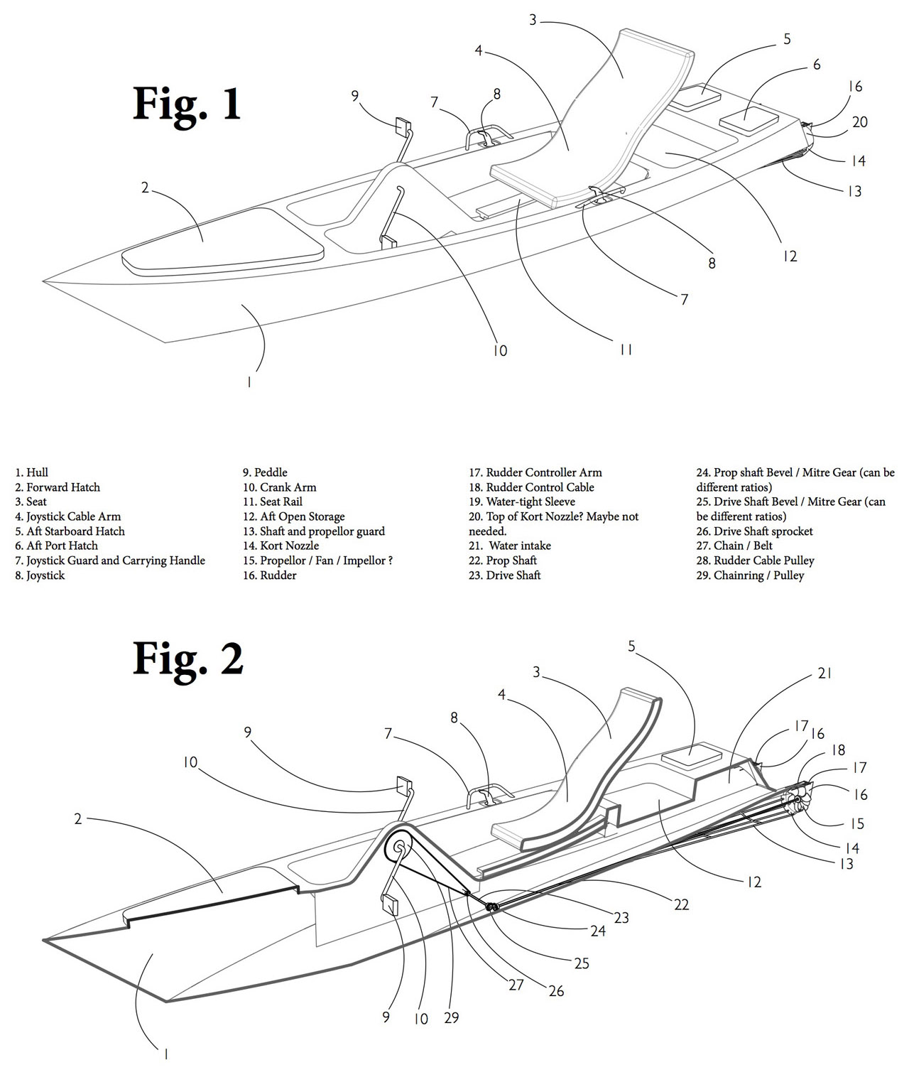
FIG. 1 is a perspective view of the top of the kayak;
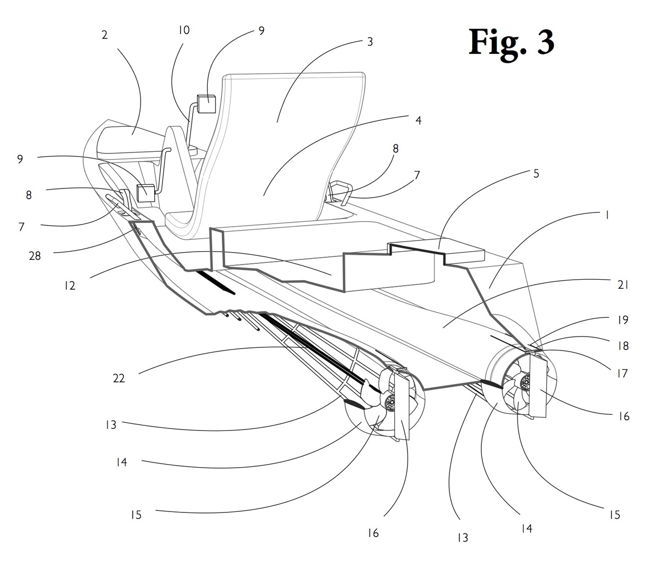
FIG. 2 is a perspective cross-sectional view of the kayak; FIG. 3 is a rear perspective tear-away view of the kayak;
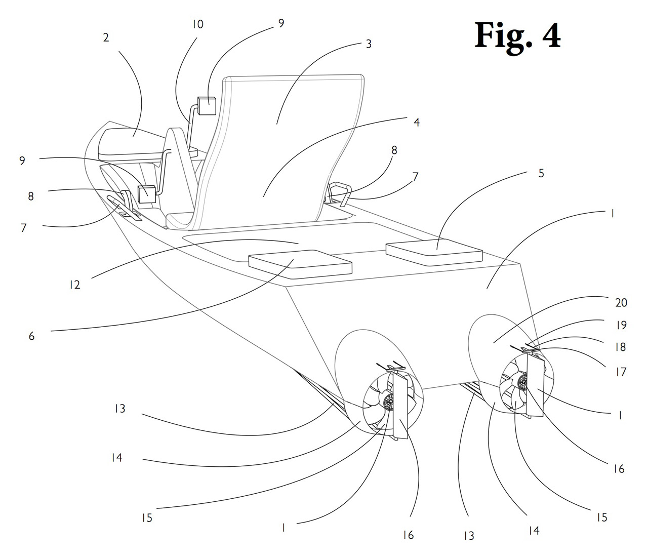
FIG. 4 is a rear perspective view of the kayak;
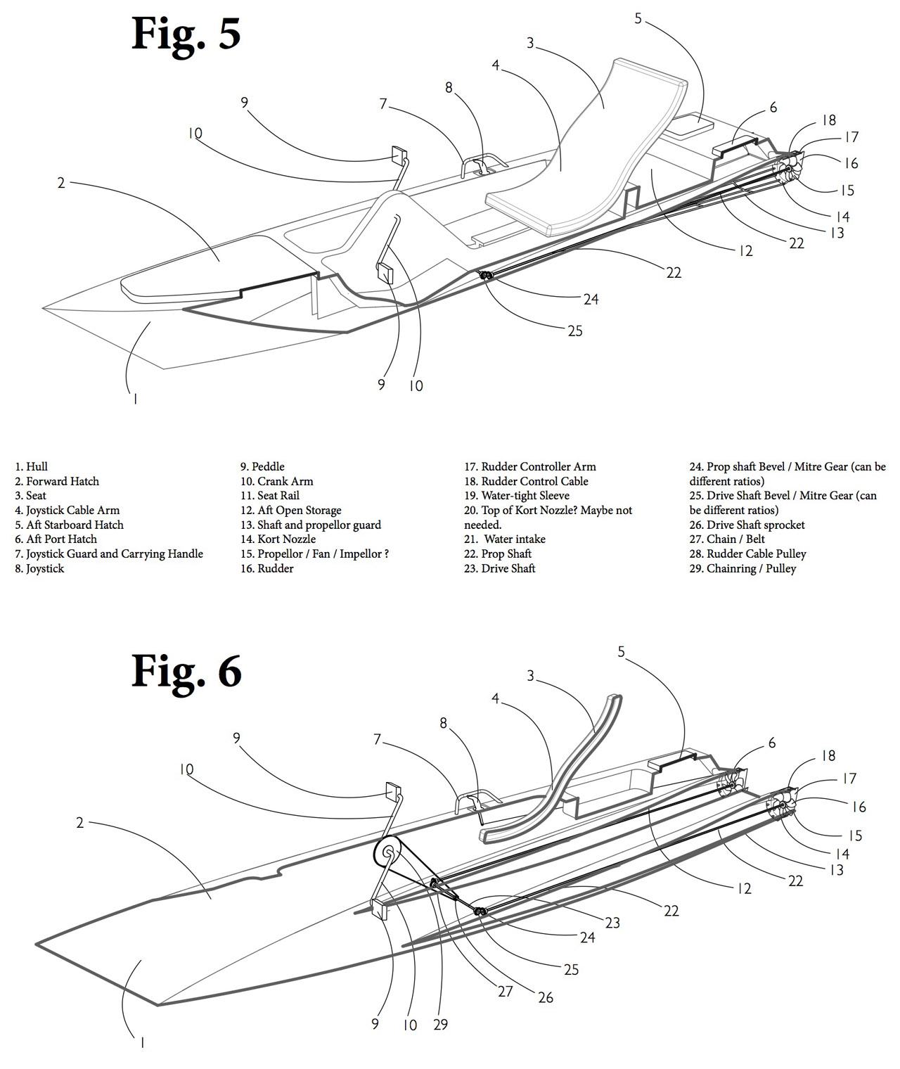
FIG. 5 is a perspective cross-sectional view of the kayak with shaft system;
FIG. 6 is a perspective 3⁄4 cross-sectional view of the kayak with shaft and gear assembly;
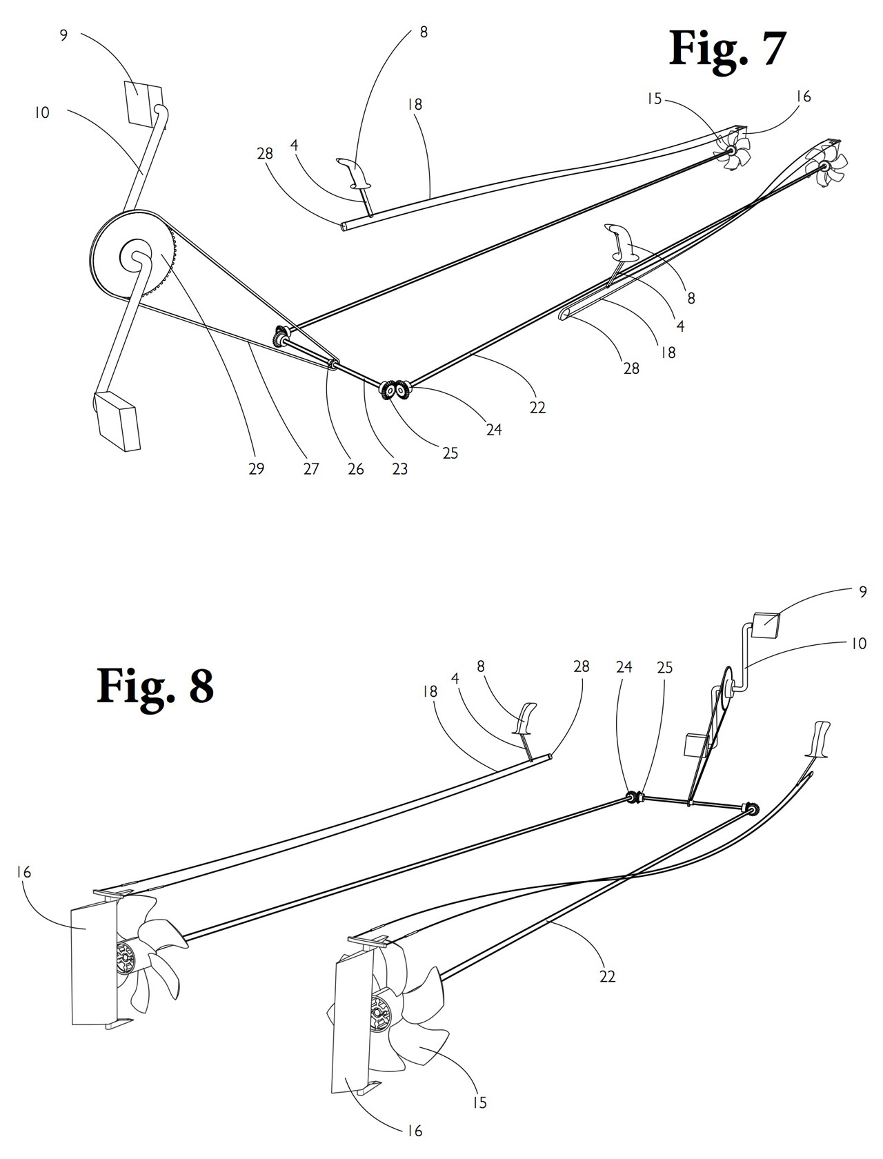
FIG. 7 is an isolated front perspective view of the gear assembly, shaft system, and dual linkage system;
FIG. 8 is an isolated rear perspective view of the gear assembly, shaft system, and dual linkage system.
DETAILED DESCRIPTION
Embodiments of the present invention are described herein in the context non-submersible watercraft, specifically kayaks. Those of ordinary skill in the art will realize that the following detailed description of the present invention is illustrative only and is not intended to be in any way limiting. Other embodiments of the present invention will readily suggest themselves to such skilled persons having the benefit of this disclosure. Reference will now be made in detail to implementations of the present invention as illustrated in the accompanying drawings. The same reference indicators will be used throughout the drawings and the following detailed description to refer to the same or like parts.
The present invention comprises a plurality of cranks, shafts, pulleys, sprockets, bevels, cables, levers, intake reservoirs, joysticks, carrying handles, seat, and hull. The kayak is designed to cruise at an average speed of 6 knots, while being able to achieve speeds in excess of 8+ knots in bursts. The mean number of pedals per minute for the average road cyclist is between 60-80 RPM. However, when in a sprint, or trying to “top-out,” that number will increase to 100-120 RPM. In the present embodiment, the gearing is set to 1:18, producing the shafts to turn at 1080-1440 RPM and 1800-2160 RPM respectively. These high RPMs exist since the propeller is closer in resemblance to a turbine or ducted fan.
The Hull (1) is designed to be created out of ABS plastic to design specifications, but can be made from other high-end materials commonly found in kayaks. The cavity for the chain ring and gear assemblies will be hollowed out within the hull according to manufacturer’s specifications, allowing ample room for the spindle, pedals, and other components (29).
The Forward Hatch (2) provides a recessed compartment to safely store and shield personal goods and other equipment from the water while the kayak is in use. The Forward Hatch is convenient and easy to use because it is located directly in front of the user and cockpit. The measurements of the Forward Hatch are variable based on design specifications or custom builds.
The Top and Bottom Seat (3 and 4) provides a seating area for the operator. The Top and Bottom Seat form one solid unit which is fixedly attached to the Seat Rail (11) by a sliding attachment. The attachment means on the underside of the seat possess a locking attachment capable of unlocking the seat from the sliding attachment. This allows the seat to be detached from the kayak for transport.
The seat is situated within a recess at the back of the cockpit specifically molded into the upper deck of the kayak. This allows the user’s hips to remain completely below the upper deck. The seat can be made from a variety of plastics, rubbers, fabrics, and other materials. The measurements of the seat are variable based on design specifications or custom builds.
The Aft Starboard Hatch (5) functions as a recessed compartment to safely store and shield personal goods and other equipment from the water while the kayak is in use. The Aft Starboard Hatch is convenient and easy to use because it is located directly behind the right side of the user. The measurements of the Aft Starboard Hatch are variable based on design specifications or custom builds.
The Aft Port Hatch (6) functions as a recessed compartment to safely store and shield personal goods and other equipment from the water while the kayak is in use. The Aft Port Hatch is convenient and easy to use because it is located directly behind the back left side of the user. The measurements of the Aft Port Hatch are variable based on design specifications or custom builds.
The Joystick Guard / Carrying Handle (7) is fixedly attached to the side of the hull by an attachment means. It provides protection to the Joystick (8) by extending above and around the height and length of the Joystick. It also provides a method for manual transportation of the kayak by hand. The Joystick Guard / Carrying Handle can be made from a variety of metals or plastics.
The Joystick (8) is a steering mechanism that controls the rudders (17) via cable linkage. The Joystick is fixedly attached to the cable linkage by an attachment means. Tilting the joystick either left or right turns the rudders in the respective direction. Moving the joystick forwards and backwards will also move left and right. The Joystick can be made from a variety of metals or plastics.
The Pedals (9) are rotationally attached by an attachment means to the outside end of the Crank Arm (10). The pedals manually rotate the Crank Arm (10) in order to generate power for the propulsion system. The Pedals can be made from a variety of metals or plastics.
The Crank Arm (10) provides power to the propulsion system via pedal-power. At one end, the Crank Arm is fixedly attached by an attachment means to the center of the Chain Ring (29). At the other end, the Crank Shaft is rotationally attached by an attachment means to the pedals (9). The Crank Arm can be made from a variety of metals or plastics.
The Seat Rail (11) is fixedly attached by an attachment means on its underside to the inside surface of the hull. The Seat Rail provides a surface upon which the bottom seat may be fixedly attached. The seat rail allows the seat to traverse forward and backward movement, creating ease and variable positions of operation for the user. This allows for a maximum range of motion while operating the kayak. The Seat Rail can be made from various metals or plastics.
The Aft Open Storage (12) functions as recessed compartment to safely store and shield personal goods and other equipment from the water while the kayak is in use. The Aft Open Storage is convenient and easy to use because it is located directly behind the user and left open for accessibility purposes.
The Shaft and Propeller Guard (13) is a rigid wire-framed housing unit that provides protection for the Prop Shaft (22) and Propellers (15) from damage by the water bottom and other debris while also aiding in decreasing the draft of the kayak. These positive effects are increased by the combined affects of the Kort nozzle housing system (14). At one end, the Shaft Guard is attached by an attachment means to the inside perimeter of the Kort nozzle (14). At the other end, the Shaft Guard is fixedly attached to the underside of the hull on the opposite end by an attachment means directly underneath the point at which the drive shaft and prop shaft converge. The Shaft Guard extends a predetermined length between the Kort Nozzle (14) and the point at which the Drive Shaft and Propeller Shaft converge. The Shaft and Propeller Guard can be made from a variety of metals or plastics.
The Kort Nozzle (14) is designed for efficiency as well as protection for the propellers. The Kort Nozzle is created from two separate mechanisms that are fixedly attached by an attachment means on its bottom end to its opposite upper end. The bottom mechanism is a metallic grate that is fixedly attached to the solid plastic upper end. The upper mechanism is designed directly into the hull for ease in manufacturing. As shown in Fig. 3, the bottom grate is connected to the upper nozzle (Part 20). It is this unique combination of propellers and nozzle that produces maximum efficiency. The nozzle diameter is approximately 6 inches. The Kort Nozzle can be made from a variety of metals or plastics.
The Counter-Rotating Propellers (15) are fixedly attached inside a wire-frame housing of the Shaft and Propeller Guard (13). The propellers are Kaplan style, five-blade, flabellate propellers. The propellers may be manufactured from cast aluminum with steel pins and brass tubes or other predetermined combinations of metal or plastic parts.
The Rudders (16) control and steer the kayak. The rudders control the kayak by directing the output propulsion through the Kort nozzles (14) on both ends. The direction of the kayak is determined by the angle at which the rudders thrust the water outward. The angle at which the rudders thrust water outward is determined by manual operation of the Joystick (8). The rudders cause the boat to turn in the direction opposite that of the output propulsion. In tight situations, where technical navigation is required, the shafts can be both or alternately reversed in conjunction with the rudder position to provide the kayak with unparalleled maneuverability. Each rudder is fixedly attached by an attachment means that connects the rudder to a Joystick (8) located on both sides of the kayak. The Rudders can be made from a variety of metals or plastics.
The Rudder Controller Arm (17) is fixedly attached by an attachment means on the outside of its top and bottom ends to the inside of the top and bottom ends of the Kort nozzle (14). The function of the Rudder Controller Arm is to change or maintain the angle at which the rudder is positioned, thus determining the direction of the kayak. The Rudder Controller Arm can be made from a variety of metals or plastics.
The Rudder Control Cable (18) allows the operator to control the position of the Rudders (16) via the Joystick (8). At one end the Rudder Control Cable is fixedly attached to the end of the Rudder (16). At the other end, the Rudder Control Cable is fixedly attached to the Joystick (8). The Rudder Control Cable extends a predetermined length than is fixedly attachment to the hull by an attachment means. The Rudder Control Cable can be made from a variety of metals.
The Watertight Sleeve (19) is fixedly attached by an attachment means to outside of the Kort nozzle (14). The Sleeve comprises a sleeve impermeable to water extending from the Rudder Control Arm (17) throughout the hull to the Joystick (8). The Rudder Control Cable (18) is contained within the impermeable sleeve in order to keep the control cables free from moisture. The Watertight Sleeve can be made from a variety metals, plastics, or rubbers.
The Water Intake (21) is a hollow channel in which and out of which water passes through for the purpose of producing water pressure used to power the propulsion system. The Water Intake extends a predetermined distance calculated by design specifications.
The Prop Shaft (22) receives force transmitted from the Drive Shaft (23) and applies rotational force to the Propellers (15). The Prop Shaft extends a predetermined distance from the Prop Shaft Bevel (24) to the Propellers (15). At one end, the Prop Shaft is rotationally attached to the Prop Shaft Bevel (24) via a coupling mechanism. At the other end, the Prop Shaft is rotationally attached to the Propellers (15) via another coupling mechanism. The Prop Shaft can be made from a variety of metals.
The Drive Shaft (23) receives rotational force generated by the Crank Shaft (10) and mechanically transmits said force to the Prop Shaft (22). At one end, the Drive Shaft is rotationally attached to the Prop Shaft (22) via a coupling mechanism (25). At the other end, the Drive Shaft is rotationally attached to the Chain Ring (29) via a coupling mechanism (26). The Drive Shaft can be made from a variety of metals.
The Prop Shaft Bevel (24) connects the Prop Shaft (22) to the Drive Shaft Bevel (25) via a series of coupling mechanism. At one end, the Prop Shaft Bevel is rotationally attached to the Prop Shaft (22) by an attachment means. At the other end, the Prop Shaft Bevel is rotationally attached to the Drive Shaft Bevel via a coupling mechanism. The Prop Shaft Bevel can be made from a variety of metals or plastics.
The Drive Shaft Bevel (25) connects the Drive Shaft (22) to the Prop Shaft Bevel (24) via a series of coupling mechanism. At one end, the Drive Shaft Bevel is fixedly attached to the Drive Shaft (23) by an attachment means. At the other end, the Drive Shaft Bevel is rotationally attached to the Prop Shaft Bevel (24) via a coupling mechanism. The Drive Shaft Bevel can be made from a variety of metals or plastics.
The Drive Shaft Sprocket (26) is a coupling mechanism that transmits force between the Drive Shaft (23) and the Crank Shaft (10) via the Chain Ring (29). At one end, the Drive Shaft Sprocket is fixedly attached to the Drive Shaft (23) by an attachment means. At the other end, the Drive Shaft Sprocket is fixedly attached to the Chain Ring (29) by an attachment means. The Drive Shaft sprocket can be made from a variety of metals or plastics.
The Chain Belt (27) is a pulley mechanism that transmits force generated by the by the Crank Arm (10) to the Drive Shaft (23) via the Drive Shaft Sprocket (26). At one end, the Chain Belt is rotationally attached to the Chain Ring (29) via a coupling mechanism. At the other end, the Chain Belt is rotationally attached to the Drive Shaft Sprocket (26) via a coupling mechanism. The Chain Belt can be made from a variety of metals or plastics.
The Joystick Lever Arm (28) provides a base of support for the Joystick (8). At one end, the Joystick Lever Arm is fixedly attached to the underside of the Joystick Arm (8) by an attachment means. At the other end, the Joystick Lever Arm is fixedly attached to the Rudders (17) via cable linkage. The Joystick Level Arm can be made from a variety of metals or plastics.
The Chain Ring assembly (29) transmits force generated by the Crank Arm (10) to the Drive Shaft (23) via a series of coupling mechanism and spindle. At one end, the Chain Ring is fixedly attached to the Crank Arm (10) by an attachment means. At the other end, the Chain Ring is rotationally attached to the Chain Belt (27) via a coupling mechanism. The Chain Ring can be made from a variety of metals or plastics.
From the Chain Ring (29) to the drive shaft (23) there is an 18:1 gear ratio. This means for every 1 revolution of the Chain Ring, the drive shaft will have produced 18 revolutions. This allows for a greater amount of thrust coming out of the propellers while at the same time lightening the force required at the Chain Ring. The Chain Ring must be enclosed within the cavity shown in figs. 2 and 6 to both protect the legs of the operator and maintain the integrity of the chain and gears. This creates a barrier between the metal parts and the harsh, shallow environment within which kayaks operate.
The present invention is significantly different from kayaks that use traditional propulsion system in that it utilizes a Kort nozzle propulsion system. The present invention utilizes the Kort nozzle propulsion system to eliminate a number of problems created by a design flaw inherent in kayaks with traditional propulsion systems.
The Kort nozzle system applies the principle of hydrodynamics to the propellers by housing them within an enclosed structure that increases both thrust and control. The velocity of incoming water increases by entering the Kort nozzle system. This increases the overall pressure on the propellers, specifically increasing the thrust and torque. Simultaneously, the Kort nozzle causes the water to circulate inwardly through the fixed intake of the Kort nozzle. Because of the unique design of the Kort nozzle, the inward thrust created by the circulation of incoming water creates an increase in forward thrust greater than the pressure that reduced the thrust on the propeller from the increased velocity of the incoming water. The result is a net increase of forward thrust that significantly and positively affects the speed and maneuverability of the kayak.
The net increase in forward thrust and maneuverability created by the unique design of the Kort nozzle system remains constant at lower speeds, and only increases the drag enough to negate the positive affects at higher speeds. This is significant because Kort nozzles are more efficient than exposed propellers at relatively low speeds, making them ideal for kayaks which rarely achieve the speeds necessary to make the Kort nozzles inefficient. This results in increased thrust and accuracy in maneuverability for almost all users.
The first limitation the present invention eliminates is prop drift. Prop drift leads to decreased stability and maneuverability. In order to eliminate prop drift, it is crucial to the design of the present invention that there be two drive shafts that connect to two counter-rotating propellers. Counter- rotation is essential in eliminating prop drift that affects traditional propulsion systems. The dual drive shafts and propellers direct the flow of water from the nozzle in both directions and allows for navigation by engaging the direction of thrust on either side of each propeller. This allows the port prop shaft to be engaged in a forward direction while the starboard prop shaft can be engaged in a backward direction regardless of rudder direction with the result that the boat will turn starboard. This results in more efficient and advanced maneuvering techniques over single prop and paddle watercraft that are plagued by prop drift.
The present invention also utilizes the Kort nozzle system to eliminate draft. In the present embodiment, the Kort nozzle provides a housing system that encloses the propellers and provides multiple functions. First, the housing system enclosing the propellers utilizes the Kort principle of hydrodynamics to increase thrust and maneuverability. This increased thrust and maneuverability counteracts the constantly changing and unpredictable behavior of turbulent waters. Second, the housing system acts as a protective barrier around the propellers, increasing safety. The protective barrier created by the Kort nozzle’s housing system protects the operator’s legs, providing maximum safety for the operators and anyone or anything in the near vicinity. Moreover, the protective barrier around the propellers preserves the integrity of the chain and gears by creating a barrier between the kayak’s metal parts and the harsh natural environment inherent in the shallow waters in which kayaks typically operate.
When in use, the present invention yields many advantages over kayaks with traditional propulsion systems. First, there is increased thrust potential. Second, there is increased maneuverability from the dual drive shafts and counter-rotating propellers. Third, there is increased accuracy while operating with said increased thrust and maneuverability. And last but not least, the Kort nozzle provides unmatched safety for operators and bystanders, while at the same time providing protection for the propulsion system.
While the above description contains specific details regarding certain elements, sizes, and other teachings, it is understood that embodiments of the invention or any combination of them may be practiced without these specific details. Specifically, although shapes and gearing are designated in the above embodiments, any shape and gearing may be used. These details should not be construed as limitations on the scope of any embodiment, but merely as exemplifications of the presently preferred embodiments. In other instances, well known structures, elements, and techniques have not been shown to clearly explain the details of the invention.
Patent Pending
2014 Lohr Designs LLC
BACKGROUND
FIELD OF THE INVENTION
This invention relates to non-submersible watercraft, and, more particularly, to single-manned kayaks which comprises a Kort-nozzle propulsion system, hull, storage compartments, joysticks, counter- rotating propellers, rudders, pedals, gear assembly, and shaft assembly.